General scheme
The general scheme of work can be seen in this figure.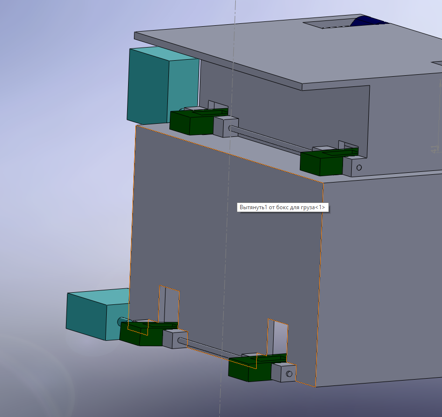
This scheme is outdated, but I bring it for a simple understanding of how it all works. At the moment, I have abandoned the different width and length of the cargo and battery boxes. This will avoid problems of skewing during loading and unloading. The figure shows the right part of the box where the battery will be unloaded and locked by the upper servo and the lower part which serves for cargo transportation and is locked by the lower servo. Also, there is no end cap on the circuit. This circuit is designed to work with control from the drone controller.
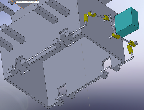
The same scheme was not completed later and is more realistic. The only servo hanging in the air is necessary for its attachment to be removed and will be attached later.
What the scheme looks like in practice can be seen on the example of a drone 250 250mm racing drone